
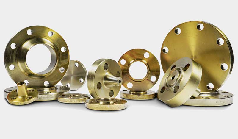
Flange and its applications
A flange is a part or a tool that is used to connect pipes, close the pipe together, change the direction or change the diameter of the pipes.
This product is ring-shaped and connects pipes and fittings to valves and other equipment in a piping system using bolts and nuts.
This product is used when proper thread and welding cannot be used.
Flange connections are usually used in petrochemical industries and power plants up to a size of at least 2 inches.
Flange connections are made of cast steel and cast iron.
Steel flange connections are used instead of cast iron connections in systems with high temperature and pressure conditions.
Because cast iron tends to crack and disintegrate when exposed to certain stresses.
A flange connection is made by bolting two flanges together and a gasket to seal between them.
The types used in the petrochemical industry are: butt weld, slip-on, silent weld, ribbed flange, blind.
Application of flanges in industry and facilities
Although the cost of flange is higher than welding, the advantages of using this method have encouraged manufacturers to use these parts.
Advantages including:
Changing the size and dimensions of the pipe
Pipe connections to equipment such as pump connections, compressors, etc.
Changing the material and type of pipe
Connection to valve and other items if need to change
Connection to instrumentation equipment that requires calibration
Connection to the pipe and things that need to be separated.
Specifications of flanges
According to the standard, the specifications that include the following must be engraved on the flange:
1- The brand name of the flange manufacturer
2- Nominal size of the pipe (outer diameter of the pipe to which the flange will be welded)
3- Tolerable pressure value (it is also called flange class)
4- The shape of the flange surface (the shape of the flange surface is the most important part of a flange)
5- Holes (sometimes also expressed as wall thickness)
6- Components of the flange (according to the ASTM standard, this number expresses the specifications of the raw materials used to prepare the flange)
7- The number or code related to the heat treatment done on the flange
Types of flanges based on surface
The types of flanges are classified based on the surface, which includes flat face surface, raised face surface, male and female, tongue & grooved, edged, facing, blind flange, welded neck, chamber welding, threaded and The orifice is a flange.
Flange with smooth surface
Types of flanges with a smooth surface are usually for connecting to non-steel flanges of pumps and other equipment, as well as connecting to cast iron valves and fittings.
This flange is used for classes 150 and 300 as well as non-toxic and non-flammable fluids.
Flange with raised surface
Types of flanges with a raised surface As the name suggests, a part of the flange surface is raised to prevent material leakage.
The raised surface height is usually 1/16 inch.
Groove and tongue flange
All kinds of grooved and tongue flanges are produced in both large and small sizes.
Groove and tongue flange gasket fits in the space between the outer diameter and the inner diameter of the groove.
It protects the gasket from corrosion and decay caused by contact with liquids.
Slippan flange
The calculated resistance force of this model, under internal pressure, is ⅔ of welded throat flanges, which life is reduced to ⅓ under fatigue conditions.
The connection of this product with the pipe is done by 2 fillet welds.
The value of X in the picture is almost equal to the thickness of the pipe wall plus 3 mm.
It is necessary to maintain this distance to prevent damage to sensitive surfaces during welding.
One of the disadvantages of this flange is that the pipes must be welded first and then the connections must be adjusted with it.
It is not possible to connect a knee or a tee because the mentioned connections do not have a straight and straight end and cause slipping on the flange.
blind flange
Blind flange is a closed round plate that is used at the end of piping and pressurized routes.
Its screws bear more pressure than other models, and most of the pressure is in the center.
According to the flange class, the blind flange can withstand the appropriate pressure.
Facing flange
The facing flange is used in normal services and its installation is simple.
The resistance of the facing model against the internal pressure is two-thirds and against the fatigue load one-third of the necked flange, and its installation cost is a little higher.
Edged flange
The edged flange is like a normal flange, except that there is no lower layer and its end has a chamfer, and the pipe is butt-welded at the other end.
This model is not in contact with the fluid, its cost is one third more than the necked model and its fatigue resistance is only one tenth of the necked model.
Flange with chamber welding
A flange with a chamber weld has a chamber in which the pipe is placed.
If this product is welded from the inside, its fatigue resistance will be one and a half times and its static resistance will be equal to the Slip on flange.
Threaded flange
A threaded flange is machined into that thread and the pipe can be screwed into it.
One of the advantages of the threaded flange is that there is no need for welding.
If necessary and high pressures, welding can also be used in them, and basically the efficiency of this type of flange is at high pressures.
Orifice flange
Orifice flange is the throated flange and in some cases facing, which has a hole along the radius.
These holes are used to measure the flow of liquid or gas.
Welded throat flange
The welded throat flange has a conical neck, the radius of this neck at the end is equal to the diameter of the pipe and is welded to it.
The presence of this neck strengthens the tolerance of the flange.
This product is suitable for bearing high pressures and temperatures below zero, as well as fluctuating and vibrating loads.
Male and female flange
This product must be made in pairs, the surface of one of the flanges has a protrusion and the other surface has a recess.
which is designed according to the used position of the indentation and protrusion surface with certain proportions.
Usually 3.16 inches deep recess and material surface has 1.4 inch protrusion.
The use of male and female can be seen in the shell of the heat exchanger to the channel and cover.
Advantages and disadvantages of flanged joints
Advantages and disadvantages of flanged connections can be described as flanges provide easy access for cleaning, inspection and repairs and are usually welded or ribbed.
The advantage of flange systems is their ease of assembly and disassembly.
The fact that these connections are heavier than similar welded and threaded connections is one of the disadvantages of flanged connections.
Flanged joints take up more space than other joints.
The cost of making supports and hangers for flange systems is more than other systems.
You may have heard that the flange connection cannot be 100% sealed, which is one of the disadvantages of these connections.
Flanged pipes require more space and their insulation is expensive.
What is flange class?
The class of the flange is determined according to the material and the range of pressure and service temperature.
The higher the class, the more material is used in it, the tolerance limit is increased, the dimensions are larger and it can withstand more pressure.
In addition to the amount of material, the amount of pressure and temperature that can be tolerated by the flange also depends on the type of material used in it.
For example, class 300 withstands more pressure than class 150, and as the class increases, the number and diameter of its screws also increases.
Class with pressure classification according to ANSI B16.34 standard, based on this standard, steel flanges and its alloys are divided into classes 50-300-400-600-900-1500-2500.
Flange class with pressure classification based on ISO standard, which in this standard, steel and its alloys bearing pressure is indicated by PN, which indicates the nominal pressure in BAR.
Flange class with pressure classification based on standard (API 6A-6B-6BX), this type of them has more pressure tolerance than ANSI group and are divided into 5000-3000-2000-15000-10000 classes.
Standard metal flanges
The standard of metal flanges is usually determined by the material used.
Some of them are made of different materials such as stainless steel, cast iron, aluminum, brass, bronze.
According to the standard, metal flanges are mostly made of carbon steel, and their surface is machined, and in most cases, the material of the flange is the same as the pipe.
All flanges are usually manufactured to ASME and ASTM standards unless another standard is used.
ASME B16.5 standard defines dimensions and dimensional tolerance and ASTM A182 standard determines the material of steel flanges.
In most cases, the standard metal flanges comply with ISO standards, so the flanges are interchangeable.
Bolts and nuts used to fasten flanges
The bolt and nut used to close the flanges may be threaded on one side, which is called a bolt, on the other side, it has 6 ears or 4 ears for a wrench.
The bolts used to fasten the flanges are threaded, requiring one Nut, or may be fully threaded Stud Bolts, in which case two nuts are required.
Size and type of screw gear
The size and type of screw rib are measured in millimeters or inches based on the outer diameter of the screw.
For example, the outer diameter of a 16M screw is equal to 16 mm (the outer diameter of a 4.3 inch screw is equal to 3.4 inches).
The size and gear type of bolts and nuts are threaded according to the metric or inch system, and in both cases, the gear on the bolt is parallel.
That is, the diameter of the tip of the rib is the same along the length of the screw and the nut turns easily throughout the screw.
In the metric system, the pitch size of the screw is determined along with the outer diameter of the screw.
For example: 2*30M means the outer diameter of the screw is 30 mm and its pitch is 2 mm.
In the inch system, along with the outer diameter of the screw, the number of gears per inch is also specified.
For example: 4/3″*8″ means the outer diameter of the screw is 4/3 inches and the number of teeth per inch is equal to 8 teeth.